
The Ultimate Residential HVAC Guide
Residential Duct Starter Guide: Everything You Need to Know
Want to DIY your duct? Have a room that's always too hot or too cold? Here's how to size an HVAC unit, design the duct system to match, and build your materials list — using field-tested rules of thumb, not engineering software.
The Ultimate Residential HVAC Guide
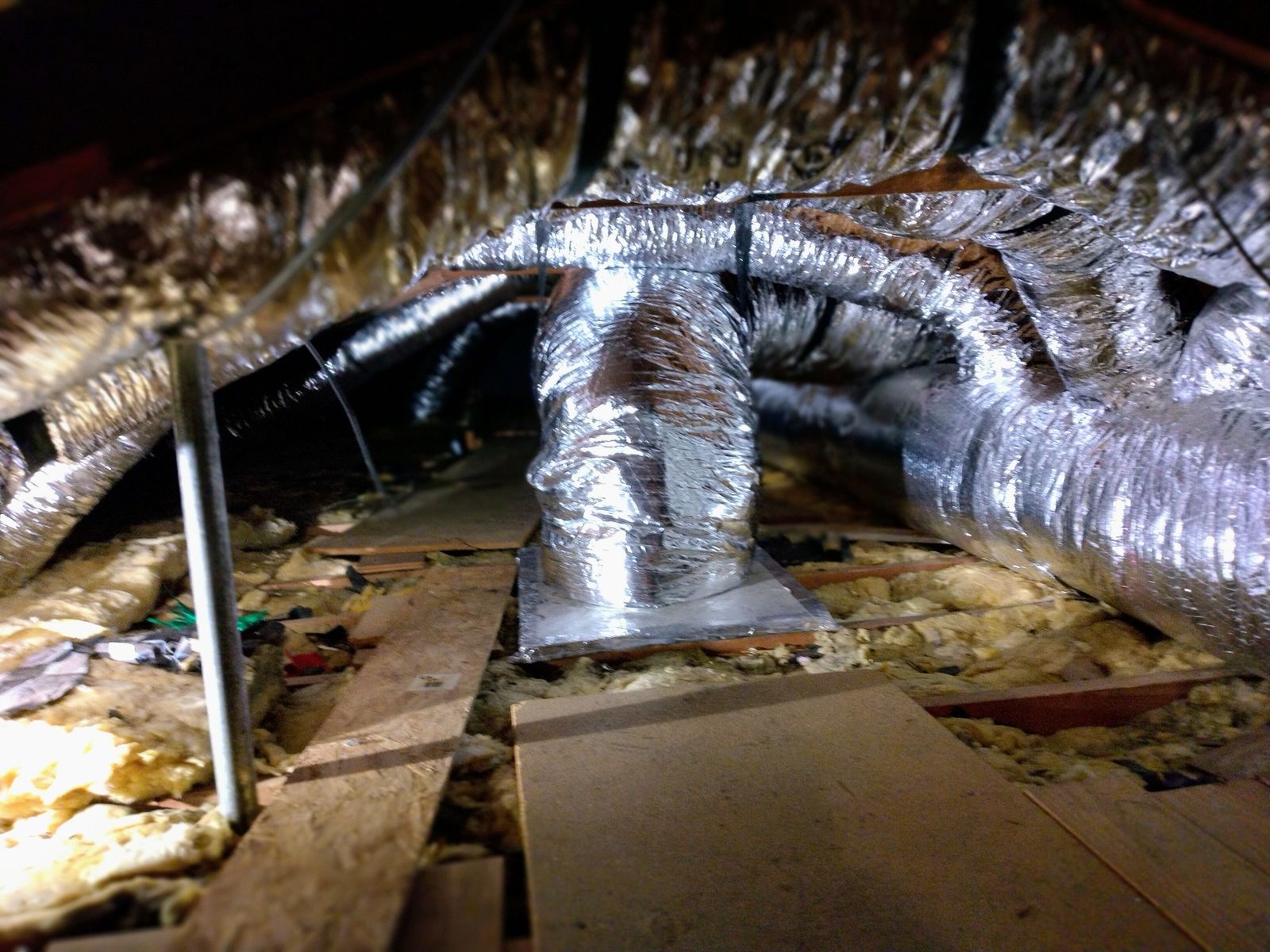
What You Will Need
Before you start designing your duct system, gather a few basics:
- A tape measure
- A pen and paper (or a spreadsheet)
- A duct CFM chart (the one below works)
That's genuinely it for the planning stage. You'll measure every room, note ceiling heights and exterior walls, and work through the steps below with simple arithmetic.
What ductwork actually does
Ductwork is the network of pipes — called duct — that connects your HVAC unit to the vents in your rooms. It distributes conditioned air evenly and efficiently while pulling stale air back for reconditioning. A well-designed system improves comfort, efficiency, and air quality. A bad one gives you hot bedrooms, high bills, and a unit that dies young.
This guide walks through the whole process: sizing the unit, choosing materials, calculating airflow room by room, laying out the trunk, and listing materials. All you need is a tape measure and a calculator.
Step 1: Size Your HVAC Unit
Unit size depends on square footage and climate. The rule of thumb that holds up in the field:
Getting this wrong hurts both ways. Too small and the unit can't keep up on the hottest days. Too big and it short-cycles — runs for five minutes, shuts off, runs again. Short cycling sounds efficient but it's not: the unit needs 15–20 minute runs to pull humidity out of the air. An oversized unit leaves you cool but clammy.
Most residential units are designed to move 400 CFM per ton of cooling. That number drives everything downstream. If you want a second opinion on tonnage, the BTU calculator at calculator.net factors in climate and insulation — but the 1-ton-per-600-sqft rule will get you in the right ballpark for most homes.
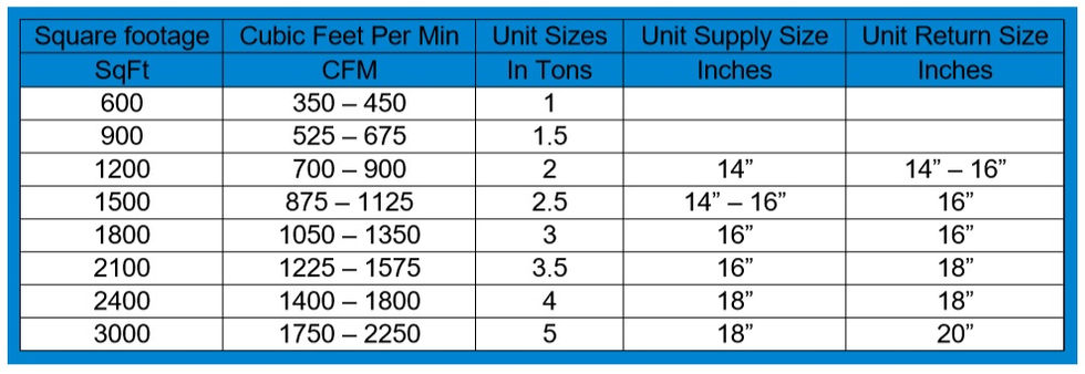
Notice the CFM values are ranges. Where your system lands in that range depends on the ductwork's friction loss and the specific equipment. Friction loss is the pressure drop caused by air rubbing against duct walls, bends, fittings, and obstructions. To minimize it:
- Select a duct material with a lower friction coefficient, such as metal
- Use a larger return — when in doubt, oversize the return side
- Avoid sharp or unnecessary bends in the duct
- Take the most direct route from unit to vent
Lower friction gets you toward the top of the CFM range, which means smaller ducts can do the same job. If you want to cross-check your numbers, the Engineering Toolbox duct sizing guide is a solid free reference.
Step 2: Choose Your Duct Material
Two main options: metal (galvanized round pipe or rectangular) and flex (flexible insulated duct).
Metal is strong, durable, fire-resistant, and easy to seal. It also has the lowest friction, so air moves through it most efficiently. Downsides: more expensive, heavier, noisier, and it needs separate insulation in unconditioned spaces.
Flex is lightweight, inexpensive, pre-insulated, and quiet. Downsides: higher friction (air doesn't glide through a corrugated interior), more fragile, and it has to be pulled tight — saggy flex kills airflow.
Most residential jobs use a mix: metal for the trunk, flex for the branch runs. If you use flex for runs, stretch it drum-tight. Every sag is a pressure drop you didn't plan for. Lowe's has a decent ductwork buying guide if you want to compare materials side by side before you buy.
Step 3: Calculate Airflow for Every Room
Each room needs a specific amount of air. The field rule:
This assumes 8-foot ceilings, average insulation, a couple of windows, and no more than one exterior wall. Adjust up for tall ceilings (multiply by ceiling height ÷ 8), big west-facing windows, or poor insulation. Kitchens and bathrooms need less for comfort but still need ventilation.
Place supply vents near windows and doors on exterior walls — this is called washing the windows, and it counteracts the heat gain/loss right where it enters. Put returns toward the center of the house, away from the furnace, kitchens, and bathrooms. The Engineering Toolbox air-change calculator can help you sanity-check room-by-room numbers if you want more precision than the rule of thumb.
Tired of doing this by hand?
Pinpoint Duct Calculator sizes every room, lays out the trunk, and builds your materials list automatically. Coming soon.
Get Notified at LaunchStep 4: Size Ducts with the CFM Chart
The next step is to choose the size of your ducts based on the airflow requirements of your HVAC unit and the length of your ducting. The size of your ducts affects how much air can flow through them and how fast it can travel. If your ducts are too small, they can restrict airflow, cause pressure drops, reduce efficiency, and create condensation. If your ducts are too large, they can reduce airflow velocity, cause uneven distribution, and increase energy waste and even cause condensation in your attic or crawlspace.
To choose the right duct size for your home, you need to consider the capacity of your HVAC unit, the number and location of your vents, and the friction loss caused by bends, fittings, and obstructions in your ducts. You can use this online calculator to help you determine the optimal duct size for your system: Engineering Toolbox duct sizing calculator. Alternatively, you can use this chart below as a reference:
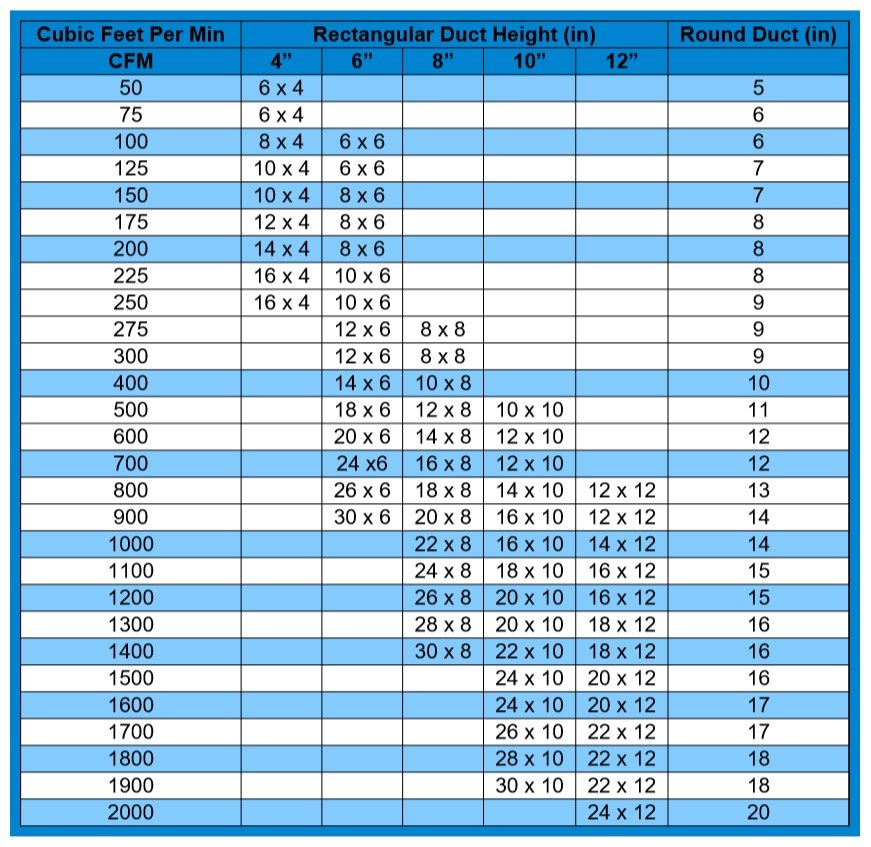
Quick reference for the most common branch runs:
| Round Duct | CFM | Typical Use |
|---|---|---|
| 5″ | 50 | Small bathroom, closet |
| 6″ | 100 | Small bedroom, office |
| 7″ | 150 | Average bedroom |
| 8″ | 200 | Large bedroom, living room |
If you're running flex instead of metal, consider going one size up on long runs — flex has higher friction and the chart assumes smooth metal.
Step 5: Design the Trunk Layout
The next step is to design your duct layout based on the floor plan of your home, the duct size, and the airflow balance. Your duct layout should be simple, direct, and balanced. This means that you should avoid unnecessary bends, branches, or splits in your ducts that can cause turbulence, noise, and energy loss.
You should also ensure that your ducts are properly insulated and sealed to prevent heat loss or gain and air leaks. Additionally, you should make sure that your ducts have enough supply and return vents to provide adequate airflow and maintain pressure balance in your system. You should also place your vents strategically to ensure even distribution and avoid hot or cold spots in your rooms. Placing vent in front of windows is considered good practice and is commonly referred to as washing the windows.
You can use this online tool to help you design your duct layout: ductworkinstallation.com duct design tool. Alternatively, you can use this simplified duct system pictured below as an example:
The trunk (or trunk line) is the big duct leaving the unit. Branch runs tap off it to feed individual rooms. The key principles:
- Start at full size. The trunk starts at the diameter the chart calls for at the unit's full CFM. Never undersize the start.
- Step down as branches take air. After several runs tap off, the remaining CFM drops — reduce the trunk diameter to match. This keeps air velocity up.
- Stagger your takeoffs. Don't put two taps directly across from each other. Offset them at least 12 inches so they don't fight for air.
- Leave the end alone. The last 1–2 feet of trunk gets no taps. This dead zone lets the system pressurize.
Returns work the same way in reverse. Size the return trunk to carry at least as much CFM as the supply — when in doubt, oversize the return. A choked return is the #1 cause of high static pressure and poor performance.
Example: 2.5-Ton System
Let's put it together. A 2.5-ton unit on a ~1,500 sq ft home moves roughly 875–1,125 CFM.
- Start: 16″ supply trunk (handles 875–1,125 CFM).
- Take a 7″ run (150 CFM) and a 5″ run (50 CFM) off the first section. Remaining: ~675–925 CFM.
- Step down to 14″. Take three 6″ runs (300 CFM total). Remaining: ~375–625 CFM.
- Step down to 12″. Take two 7″ runs (300 CFM) and two 6″ runs (200 CFM). Remaining: roughly ±125 CFM — right in the back-pressure sweet spot.
- Return: 16″ return trunk, sized to carry 1,300–1,500 CFM — comfortably above the supply total.
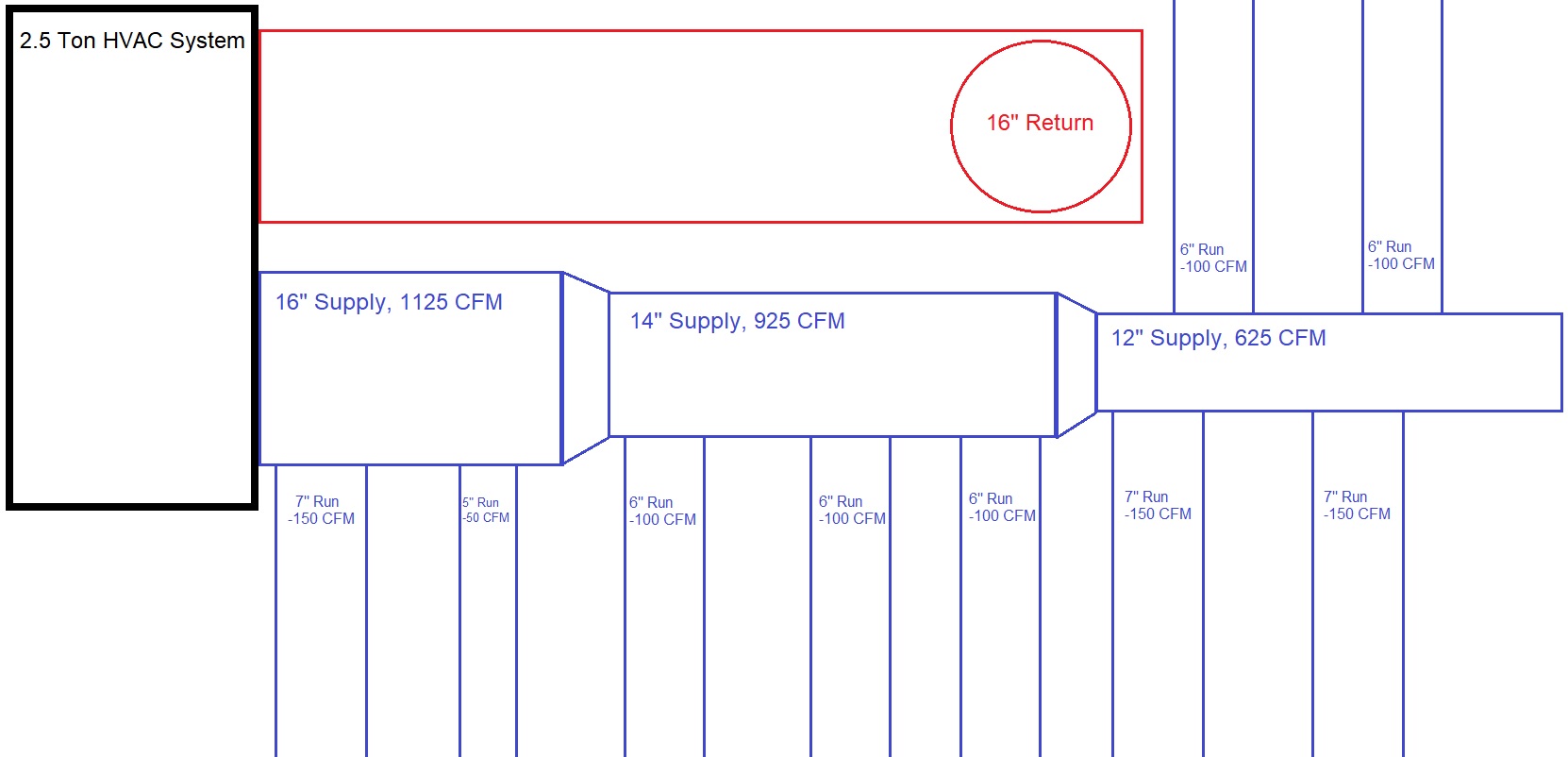
That's a complete system: unit sized, every room fed, trunk stepped down properly, back-pressure maintained, return oversized. From here it's just materials.
This took five minutes to read. The app does it in two.
Enter your rooms, get the full design — trunk sizes, branch runs, materials, and a printable proposal.
Get Notified at LaunchStep 6: Build Your Materials List
The final step is figuring out exactly what to buy based on your duct layout. Walk the design room by room, section by section, and count fittings. Here's what each part of the system needs:
Each branch run requires
- Takeoff fitting — R-AT (rounded face, for round trunk lines) or AT (flat face, for square/rectangular trunk lines). Also called taps.
- Damper — R-AT or AT damper for balancing airflow to that room. Required by building codes in some locations; good practice everywhere.
- Duct — one bag of flex per 25 feet of run length, or adequate length of metal pipe (sold in 5-foot lengths) with insulation.
- Boot — floor boot or ceiling boot, the fitting the air actually comes out of.
- Grille or diffuser — the visible register cover.
The supply trunk requires
- Adequate length of metal duct plus insulation
- Reducers wherever the trunk steps down in diameter
- Square-to-round unit adapter (connects the air handler to the trunk)
- End cap for the far end of the trunk
The return requires
- One bag of flex per 25 feet of return length, or adequate length of metal pipe with insulation
- Sheet of galvanized metal (for the return plenum/box)
- AT fitting the same size as your return duct
- Square-to-round unit adapter
- Return grille (sized to the return — bigger is better here)
Other materials
- Mastic or UL-listed aluminum foil tape (for every joint — not cloth duct tape)
- Flex or metal hanging strap
- 1/4″ sheet metal screws (zip screws)
- 2″ sheet metal screws
- Insulation (for any duct in unconditioned space)
Final Thoughts
Ductwork is the circulatory system of your HVAC — it determines whether that expensive unit actually delivers comfort to every room or just blows hard in the hallway. The rules of thumb in this guide will get you a working system for the vast majority of residential jobs.
Two things to always remember: check your local building codes before starting any work (damper requirements, insulation R-values, and permit rules vary), and when in doubt, oversize the return. A generous return forgives a lot of sins elsewhere in the system.
Glossary of Terms
- HVAC
- Heating, Ventilation & Air Conditioning.
- Unit
- The heating and air conditioning system itself — the air handler, condenser, or furnace.
- Ductwork
- The network of pipes, commonly called duct, that connects your HVAC unit to the vents in your rooms.
- Supply
- The primary pressure (output) duct of a duct system. Also called the trunk line.
- Return
- The suction (input) duct of a duct system — carries room air back to the unit.
- Run
- A secondary pressure (output) duct of a duct system — the branch from trunk to room.
- Trunk / trunk line
- The main supply (or return) duct leaving the unit. Branch runs tap off it.
- Branch run
- The smaller duct from the trunk to an individual room's vent.
- Takeoff
- The fitting where a branch run connects to the trunk.
- Boot
- The floor or ceiling register fitting that air exits from.
- AT
- Flanged duct connection with a flat face, for attaching to square trunk lines. Also called taps.
- R-AT
- Flanged duct connection with a rounded face, for attaching to round trunk lines. Also called taps.
- Flex
- Flexible vinyl-lined fiberglass insulated duct with aluminized heat shield.
- Flex hanging strap
- Cloth (generally nylon) hanging strap for flex duct.
- Metal hanging strap
- Strap used when hanging metal duct. Commonly called plumber's strap.
- CFM
- Cubic feet per minute — the standard measure of airflow.
- Ton
- 12,000 BTU/hr of cooling capacity — the heat absorbed melting one ton of ice in 24 hours. Roughly 400 CFM per ton.
- Back-pressure
- Extra CFM capacity left at the end of the trunk (100–250 CFM) that keeps the whole system pressurized so every branch gets its share.
- Washing the windows
- The practice of placing supply vents above or below windows on exterior walls, counteracting heat gain/loss at the source.
- Sheet metal screw
- Used to connect pieces of sheet metal. Also called zip screws.
- Static pressure
- The resistance the blower works against. High static = restricted ducts, dirty filter, or undersized return.